Factory Specs & Quotes
Get unbranded (white-label) PDF datasheets and custom MOQ options directly from our engineering team. Fast 24-hour response. 100% Privacy Guaranteed. No spam.

A high-power IEEE 802.3bt PoE++ splitter enables legacy and non-PoE 12V DC devices to be seamlessly integrated into modern PoE infrastructures without requiring dedicated local power. By converting a standard 44–57V PoE input into a regulated 12V DC output of up to 5A at the network edge, it delivers reliable power over standard 100-meter Ethernet links while simplifying installation, reducing wiring complexity, and improving deployment flexibility in industrial, surveillance, and enterprise networks.
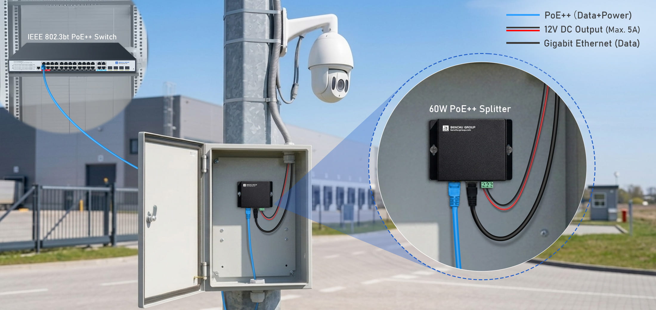
Deploying legacy 12V DC field loads over modern Ethernet networks requires addressing severe copper resistance line loss and destructive outdoor transient surges:
1. Ohmic Loss Mitigation Beyond 50 Meters
Native 12V DC transmission over copper field wiring causes severe voltage sags beyond 50 meters, dropping terminal voltage below 9.5V DC and triggering device reboots under peak loads. Transporting power at 54V DC via IEEE 802.3bt high-power PoE networks exponentially reduces loop current density, eliminating copper line power dissipation ($P_{loss} = I^2R$). This high-voltage delivery architecture guarantees a stable, continuous 12V 5A DC output at the absolute 100-meter Ethernet link limit.
2. 3500V (3.5KV) Galvanic Isolation Protection
Industrial outdoor deployments require a 3500V DC galvanic isolation barrier to decouple ground loops and suppress transient lightning surges. By integrating optical decoupling components and magnetic isolation transformers inside the 60W PoE++ splitter, the 54V PoE input stage is physically and electrically isolated from the 12V DC output stage, safeguarding expensive downstream edge hardware from destruction.
The electrical specifications below outline the complete power step-down and data routing pipeline across the network path:
| Deployment Stage | Physical Interface | Electrical / Data Protocol Specification |
|---|---|---|
| Power Source (PSE) | IEEE 802.3bt Switch Port | 50V–57V DC input; 4-pair power sourcing; Gigabit data layer |
| Transmission Channel | 100m Cat6 Cable Link | Max loop resistance < 19Ω; standardized T568B pinout |
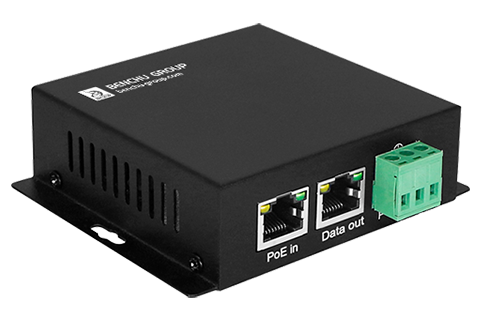
| Splitter Line In | RJ45 (PoE In) | IEEE 802.3bt Class 8 input; accepts 90W power budget |
| Power Line Out | 2-Pin Industrial Terminal | Regulated 12V DC / Continuous 5A Output (60W max) |
| Data Line Out | RJ45 (Data Out) | Pure Gigabit Ethernet data stream (Pins 1-8 clear of DC voltage) |
 |
HARDWARE SPECIFICATION
BENCHU POE-SP01-BT60W IEEE 802.3bt to Regulated 12V 5A DC Industrial Splitter
📁 Deployment: Designed for Direct Edge Conversion in High-Power Industrial Nodes
GET DATASHEET & QUOTE → |
Follow this 3-stage sequential hardware integration workflow to ensure safe electrical step-down and reliable Gigabit throughput:
|
STEP 01 — PLAN INFRASTRUCTURE
Plan the PoE Infrastructure
|
STEP 02 — EDGE DEPLOYMENT
Deploy Splitter at Network Edge
|
STEP 03 — SYSTEM VALIDATION
Validate System Performance
|
Q: Can a 60W PoE++ splitter be connected to any IEEE 802.3bt PoE switch?
A: Yes. A compliant 60W PoE++ splitter is designed to operate with IEEE 802.3bt Type 3 Type 4 PoE sources. During startup, it automatically negotiates power with the PoE switch before converting the 44–57V PoE input into a regulated 12V DC output. Always ensure the switch has sufficient PoE power budget for the connected device.
Q: Where should a 60W PoE++ splitter be installed for the most reliable deployment?
A: For best performance, install the splitter as close as possible to the powered 12V device, preferably inside a weatherproof enclosure. This keeps the low-voltage DC cable short while allowing high-voltage PoE to travel the full Ethernet distance, reducing power loss and simplifying field installation.
Deploying a 60W PoE++ splitter eliminates localized AC wiring infrastructure, mitigates long-distance line voltage sags, and secures edge deployments with 3.5KV dielectric surge isolation. Optimize your network architecture by reviewing product specs or requesting a direct engineering quote.
 راسلنا عبر البريد الإلكتروني
 اتصل بنا
 عنوان
عنوان
5F, Block5, GuangmingGu Industrial Park, Matian Villiage, Guangming Disitrict, Shenzhen, China



 شبكة IPv6 المدعومة
 بالعربية